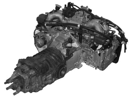
A Naturally Aspirated Subaru
EJ25 Quad Cam AVCS Engine fitted to an 091 VW Transaxle with an RJES Bell
Housing
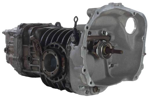
An RJES
i. Introduction:
Thanks for
buying an RJ Engineered Solutions adapter bell housing kit. This installation
guide is intended to be viewed as HTML on a web browser from the CD supplied
with the kit. This allows high resolution pictures of each stage of the
installation to be included. However, for anyone without access to a PC, a
paper copy is available on request. The pictures can
also be viewed on a DVD player, as long as it can navigate through windows
folders.
The bell
housing conversion kit is not difficult to fit. The instructions look long, but
that’s only because there is as much information included as possible. Anyone
confident enough to maintain their own old VW’s should have no problems. It
should take no more than a couple of hours (not including removing and
refitting the engine / transaxle).
These
instructions assume that you have an engine ready removed from the donor
Subaru, and have already removed the VW engine and transaxle according to the
instructions in your VW workshop manual. If removing the Subaru engine
yourself, you should buy a manual so you can find all the correct lifting
points and follow the correct safety precautions. Most breakers will lift the
engine out for you, even if you disconnect all the wires and pipes
yourself.
Note it is
highly recommended that you do remove all the wiring and plumbing yourself –
it’s you that has to put it all together again! Label everything, reconnect as
many connectors and pipes to their transducers as possible, and take lots of photo’s.
Please read
the instructions thoroughly – they are intended to give more than enough
information. If you need some information which is not included, or have any
problems not covered here, please contact us for advice.
When your
conversion is finished….
Please
e-mail any pictures you have of your completed conversion, and indicate whether
you object to then being used on the RJES web site. Thanks. It’s always
interesting to see other installations / applications.
ii. Kit
Applications:
These instructions cover two both the
naturally aspirated kit (800-00001), and the turbo kit (800-00003), as follows:
The kit is
suitable for joining the following Subaru engines:
EJ Series (All, 1.5 – 2.5 litres) 4 cylinder double or quad cam
engines, nat asp or turbo*, Phase I or II
EG 33 3.3
litre, six cylinder, quad
cam
ZE 30 & ZE30R (often known as ‘H6’) 3.0
litre ,
six cylinder, quad cam
* Kit
800-00001 is for naturally aspirated Subaru engines (with push clutches)
Kit 800-00003 is for turbo Subaru engines (with pull
clutches)
….to the
following VW transaxles:
002 …as
fitted to all Bay Window busses except 2.0 litre. Note that due to their relatively small
differentials, the 002 transaxles are nowhere near as strong as the 091 and 094
models
091 …all variants, as fitted to 2.0 litre bay window and all four speed T25 / Vanagon.
094 …as
fitted to all T25 / Vanagon 5 speed, including Syncro 4WD models.
iii. Kit Contents: The Following Components are Included in the
Kit:
Before starting to fit the parts, please read and understand this guide
thoroughly, and check that you have all of the following parts in your kit
before fitting, according to the relevant list below:
Kit
800-00001: naturally aspirated Subaru Engines:
Item No.: Part N0.: Quantity: Description:
1 002-00004 1
2 100-00020 1 Input
shaft seal, or part number 100-00055 if your bell housing was bought
with an RJES Subaru splined input shaft (fitted)
3 100-00022 1 Self
lube bush, cross shaft (fitted)
4 100-00005 2 Dowel,
engine alignment (fitted)
5 040-00006 1 Input
shaft oil removal scroll adaptor
6 * 100-00023 1 Circlip,
large
7 105-00001 2 Cap
screw M8 x 60, bell housing to transaxle
8 105-00003 2 M8
washers
9 050-00002 1 Release
bearing adaptor
10 012-00002 2 Release
bearing clips
11 100-00006 1 Pilot
bearing
12 012-00003 1 Pilot
bearing spacer
13 100-00024 1 Circlip,
small
14 105-00005 1 Screw
M10 x 25, clutch slave cylinder
bracket to bell housing
15 010-00044 1 M10
spacer washer (4mm)
16 105-00006 1 M10x1.25
x 65 stud
17 * 010-00026 3 Pressure
Plate Shims
102 900-00001 1 Instructions
CD
* Not
required if using an RJES Subaru splined input shaft
Kit 800-00003: Turbo Subaru Engines:
Item No.: Part
No.: Quantity: Description:
1 002-00004 1
2 100-00020 1 Input
shaft seal, or part number 100-00055 if your bell housing was bought
with an RJES Subaru splined input shaft (fitted)
3 100-00022 1 Self
lube bush, cross shaft (fitted)
4 100-00005 2 Dowel,
engine alignment (fitted)
5 040-00006 1 Input
shaft oil removal scroll adaptor
6 * 100-00023 1 Circlip,
large
7 105-00001 2 Bolts
M8 x 60, bell housing to transaxle
8 105-00003 2 M8
washers
9 050-00017 1 Release
bearing adaptor
10 012-00002 2 Release
bearing clips
11 100-00006 1 Pilot
bearing
12 012-00003 1 Pilot
bearing spacer
13 100-00024 1 Circlip,
small
14 105-00005 1 Screw
M10 x 25, clutch slave cylinder
bracket to bell housing
15 010-00044 1 M10
spacer washer (4mm)
16 105-00006 1 M10X1.25
X 65 stud
17 050-00007 1 Pull
clutch cross shaft
18 050-00006 1 Slave
cylinder bracket
102 900-00001 1 Instructions
CD
* Not
required if using an RJES Subaru splined input shaft
Other
Parts Needed: The Following Parts
are Needed to Complete the Installation, but are Not
Included in the kit:
Key: # Needed for naturally aspirated (push clutch) only
## Needed for turbo (pull
clutch) only
Essential
Parts: You will also need the
following parts (not supplied in the kit) before you can join your Subaru
engine and VW transaxle together:
- Subaru engine
- Subaru engine mounting
nuts / bolts / studs
- Subaru clutch pressure
plate and release bearing
- Subaru manual transmission
starter motor (see Appendix D for more starter motor info). Geared or
direct drive versions fit – those from automatic Subaru’s don’t.
- Clutch disc – see Subaru Clutch Information for details of what
you need
- VW Clutch release bearing
(retaining clips only needed) – reuse the one from your VW as long as the
clips are in good condition (only required for naturally aspirated (push
to release clutch))
- 3.5 litres
SAE 80 hypoid gear oil to MIL - L – 2105, or whatever gear oil you usually
use in your VW.
Additional
Parts: (if your Subaru Engine is from an Automatic Transmission Car:
· Flywheel from (there are different spec flywheels for
different Subaru clutches)
· Flywheel Bolts from a manual Subaru
·
· Starter Motor from a manual Subaru
Optional
Parts:
- Cross Shaft Bush / Fitting
Kit
Tools
Required:
The
following tools will be needed for the installing the bell housing kit (not including
removing and reinstalling the engine and transaxle):
- Metric socket set
- Circlip pliers – 90 degree
to suit 20mm external circlips
- Circlip pliers to suit
36mm internal circlips
- Torque wrench
- Straight edge
- VW or Subaru flywheel lock
tool (or a very large flat bladed screwdriver)
- 17mm Allen key or drain
plug tool
- Gasket scraper
- Angle Grinder (if you use
the release bearing clips from an SKF VW bearing)
- Clutch centreing
tool – VW or universal
- VW workshop manual to suit
your model
- Small gear puller – may
help to remove clutch release arm
- Solvent type degreaser
such as carburettor or brake cleaner
- Gasket compound intended
for gasketless joints, as used when rebuilding
VW engines. A thick, non setting type such as Blue Hylomar
works well.
- Lithium based general
purpose grease
- 11mm drill bit and
electric (preferably pillar) drill – needed for Phase II engines only
- Thread Lock
Installation Instructions:
1. Installation:
Bell
1.1 Drain the oil from your transaxle if you
haven’t already. Use a 17mm Allen key, or drain plug tool. No need to replace
the drain plug.
1.2 Clean your transaxle casing, especially
around the bell housing joint. A wire brush then a solvent type degreaser works
well.
1.3 Remove the bell housing from your VW
transaxle.
1.3.1 The bell housing is retained by ten M8 bolts
or nuts and studs - six inside the bell housing, and four below. Remove these.
1.3.2 Tap the
bell housing lightly with a mallet (or hammer and block of wood) away from the
transaxle to break the gasket joint. There will still be some oil in the diff
housing. Slide the bell housing off the input shaft.
1.3.3 The bell
housing is aligned with the diff housing with two 12mm dowels. They usually
stay in the transaxle casing when the bell housing is removed. If yours come
out with the bell housing, tap them out from other side with a drift, and refit
then into the holes in the transaxle casing.
1.4 If your bell housing is fitted with studs
and nuts rather than bolts, remove the highest two below the bell housing
(they’re roughly at
1.5 Carefully remove all traces of the
original gasket from the transaxle casing. The casting is very soft magnesium
and scratches very easily. Be careful not to scratch it. Pay particular
attention around the two dowels (and all the studs if your bellhousing
is mounted with studs not bolts), making sure no bits of gasket are left in the
corners.
1.6 Your oil drain plug has a
long cylindrical magnet on the back, which needs shortening. Shorten it by 13mm
with a grinder – the magnet is far too hard to be sawn. Clean all debris from
the plug and magnet. Pay particular attention to the threads – they are often
full of corroded magnesium. Fit the VW drain plug into the new bell housing,
and tighten to 19 Nm (14 ft lb). Check to make sure the
magnet does not come within 3mm of the machined bell housing face.
1.7 Tilt the transaxle slightly so the input shaft end is
at the top. This will stop oil running out.
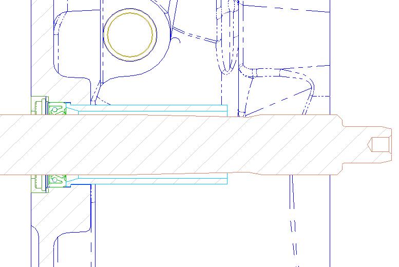
1.8 Check
the dimension from the engine mounting face to the end of the input shaft is in
the range of 151mm +/- 2mm. There are two
different lengths of VW input shaft, the long one being generally used in
petrol engined VW’s, and the short ones generally
used in diesels and turbo diesels. There is 11mm difference in length between
the long and short types, and the conversion works with both.
1.9 Clean the gasket face of the transaxle, and the input shaft
from the end to back behind the ground section that the oil seal runs on with
solvent degreaser.
1.10 Remove the
steel input shaft oil removal scroll from the VW bell housing (go to step 1.12
if you are using an RJES Subaru splined input shaft) :
1.10.1 Remove the clutch release bearing from the
release mechanism in your VW bell housing. Be careful not to damage the spring
clips which hold it on.
1.10.2 Remove the clutch release bearing guide tube
from the VW bell housing by undoing the three M7 bolts.
1.10.3 Tap the old VW oil seal out using a hammer and
drift through the input shaft hole from the transaxle side. Work around the
diameter of the seal to push it out squarely.
1.10.4 The steel input shaft oil removal scroll is a
push fit into the VW bell housing, and has to be removed from the transaxle
side, as it has a shoulder on the other end. Place the bell housing on the
bench (or floor) with the engine mounting face down. Remove the oil removal
scroll by squarely tapping it with a hammer and block of wood. Be very careful,
and do not hammer directly onto the scroll – it is very thin and will bend
easily. Use a press instead if you have one.
1.10.5 Clean the oil removal scroll with solvent degreaser.
1.11 Fit
the input shaft oil removal scroll from your VW bell housing to the adaptor:
1.11.1 Test fit the oil removal scroll into the
counterbore in the end of the adaptor. It needs to be a good fit, right down to
the bottom of the counterbore. The outer diameter of the
scrolls vary slightly, and the adaptor is designed for the smaller sized
ones. Therefore yours may be too big to fit. If so, remove material a very
small amount at a time until the scroll fits, by sanding, filing or grinding.
Be very careful to keep the scroll concentric., and not to remove any more
material than is necessary for a good push fit - tools should not be needed.
Trial fit the circlip too, to make sure it goes into it’s
groove OK. Remove the circlip and scroll.
1.11.2 Put a small amount of gasket compound in
the corner between the outer diameter and the flange at the end of the input
shaft oil removal scroll.
1.11.3 Push the oil removal scroll onto the counterbore in the end of the
adaptor, right to the bottom.
1.11.4 Fit
the circlip into it’s groove
in the oil removal scroll adaptor. Make sure it is fully in the groove so it
can’t work it’s way out.
1.12 The holes
at each end of the bore are taped over to keep dirt out of the seal. Remove the
tape which covers the input shaft hole in the bell housing. The oil seal should
be ready installed in your new bellhousing. Run a
small amount of general purpose grease around it’s
bore to lubricate the seal until oil reaches it. Be careful to make sure no
dirt gets in between removing the tape and finally fitting the bell housing
too. DO NOT slide the bell housing over the input shaft yet (for a trial fit,
etc).
1.13 Fit the oil removal scroll / adaptor assembly to the
bell housing. If you are using an RJES Subaru
splined input shaft, fit just the adaptor.
It is a push fit into the oil seal bore. Fit it by tapping or pressing
the adaptor (not the scroll itself) into place. A suitable sized socket is
ideal to reach around and the delicate scroll while fitting. Push the adaptor
into the bell housing until it stops on the shoulder.
1.14 Clean the face of the new bell housing which
closes off the transaxle casing with solvent degreaser. Clean all the bits
which will end up inside the bell housing, not just the machined face.
1.15 Wrap the input shaft with PVC insulating
tape so the splines are just covered, right to the end. Start at the splines
and work towards the end, as this will make removing the tape easier later.
1.16 Apply gasket compound to the sealing face of
the bell housing, and also the diff housing if required - follow the
instructions on your gasket compound.
1.17 Slide the
bell housing onto the input shaft, and start it on the two 12mm dowels. It
should start on the dowels easily, but probably won’t push all the way on. This
doesn’t matter as the bolts will pull it up
1.18 Loosely fit
eight of the ten original VW bell housing bolts or nuts. Turn them by hand –
not with power tools. The magnesium threads are easily damaged and difficult to
repair. Miss out the two just above the oil drain plug (at about
1.19 Tighten all ten bolts / nuts with a torque wrench to 19 Nm (14 ft lb).
1.20 Remove the insulation tape from the input
shaft.
Continue to
2 for naturally aspirated (push clutch), or 3 for turbo (pull clutch)
2. Installation:
Cross Shaft and Release Bearing – Naturally Aspirated (push clutch)
2.1 Remove the clutch cross shaft from your VW
bell housing:
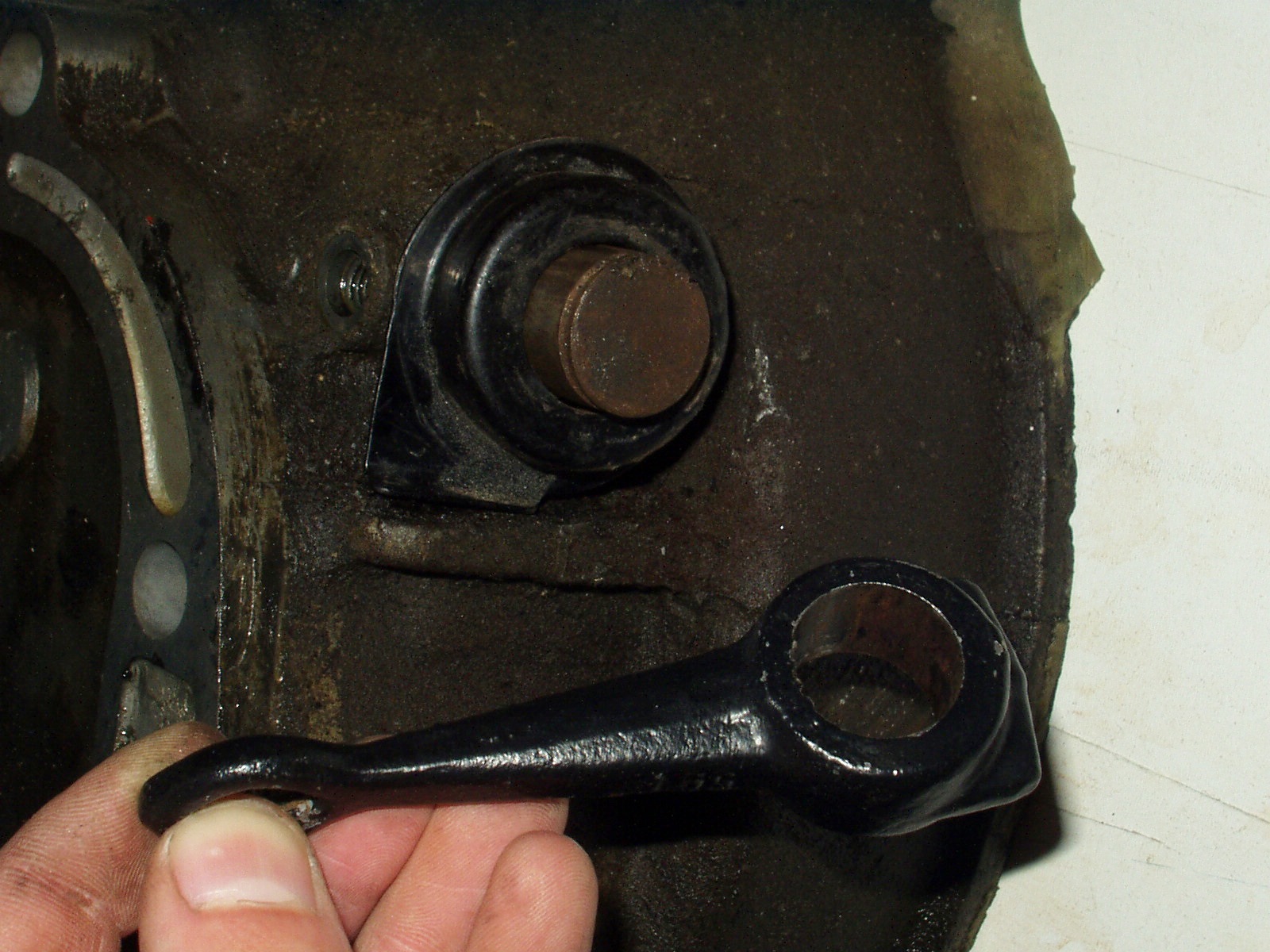
2.1.1 Un-hook
the cross shaft return spring (if your transaxle had a cable clutch) from the
release arm with a screw driver or similar. Make sure your fingers are nowhere
near the spring as you unhook it from the arm – it’s under quite a lot of
tension.
2.1.2 Remove the circlip from the end of the shaft.
2.1.3 Slide the release arm off the end of the
shaft. They can be very tight if corroded, but take care not to damage the
shaft. Heat may help if it really doesn’t want to come off, but be aware that
the bush which the shaft pivots in is plastic, as is the sleeve which it fits
into and the seals which keep the dirt out. You’ll need to replace them if you
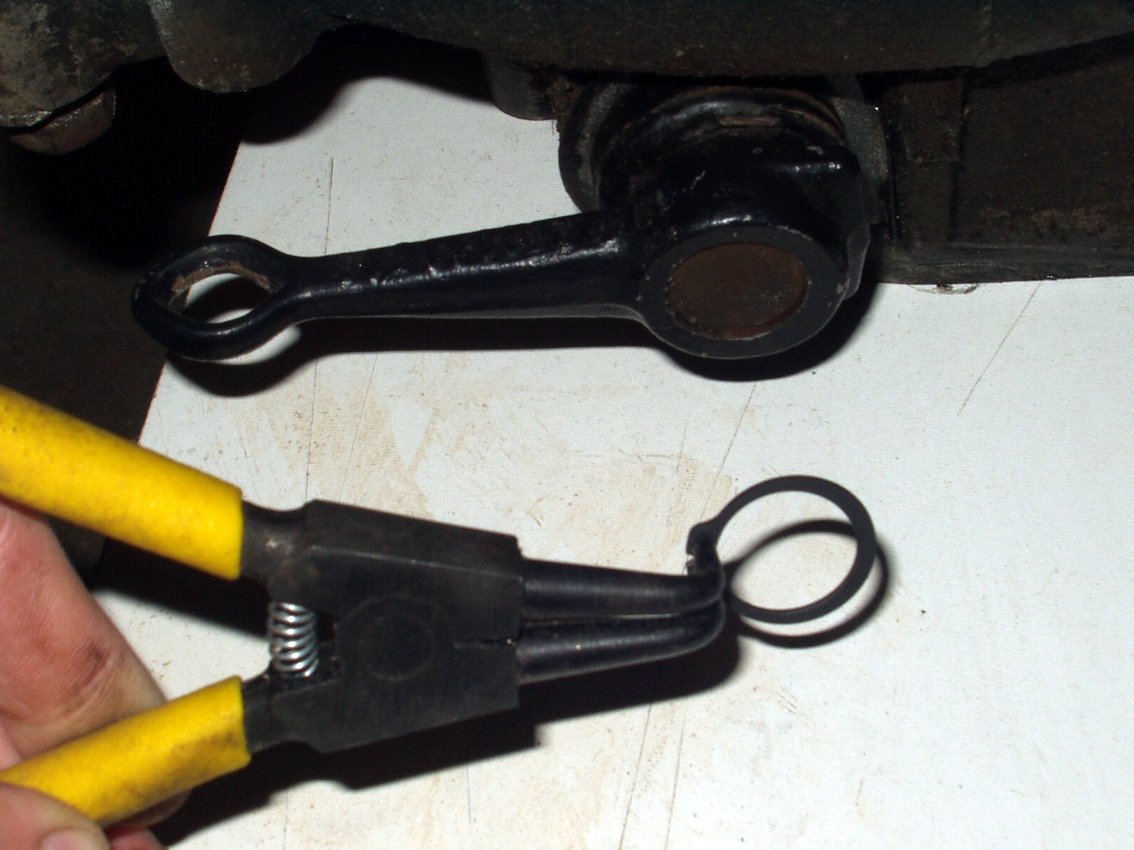
heat the arm to remove it. A puller is a
better idea. If you can’t get the puller behind the arm, undo the circlip
inside the bell housing, sliding it along the shaft. This will allow you to
slide the shaft away out to give better access for the puller. Refit the
circlip inside the bell housing back into it’s groove
once the arm is removed.
2.1.4 Remove the pressed steel spring guide if your transaxle has a
cable
clutch.
2.1.5 Remove the fabricated slave cylinder bracket
from the bell housing if your transaxle has a hydraulic clutch.
2.1.6 Remove
the threaded pin which retains the cross shaft bush from the bell housing. It’s
M8, but has an 11mm head.
2.1.7
Push the shaft assembly
out from inside the bell housing until the bush assembly is clear of the
casting. The circlip and washer will push the plastic bush assembly out of the
bell housing. They can be a very tight fit. Pull the bush assembly off the
shaft, and the steel washer between the bush assembly and the circlip (which is
still on the shaft). The bush assembly consists of an outer plastic sleeve,
with a seal, then a bush, then another seal inside.
2.1.8 Check the shaft and plastic bush for wear, and
replace as necessary. They are usually in good condition, unless they have been
damaged during removal.
2.1.9 The shaft can now be removed from the bell
housing by sliding it across until it comes out of the bronze bush at the
opposite end, tilting it, then sliding it back out of the casting.
2.2 Remove the hardened wear plates and
bearing retaining spring clips from the VW clutch release bearing:
2.2.1 The clips are just pushed on to the VW
bearing, but are quite a tight fit. If they’re badly worn where the cross shaft
fingers contact, get some better ones. Used ones are often OK, and are the same
on all ’68 – ’92 busses and ’71 à Beetles with Sachs, LUK, or VW clutches. New bearings
are not too expensive, but it’s a shame to have to buy one just for the clips.
Make sure they’re the same though if you buy a new bearing, as many modern
aftermarket parts are cheap copies, not genuine VW. Some high quality
aftermarket SKF bearings have a slightly different clip design – see 2.2.2
below. This picture shows clips
which need replacing need replacing – they’re badly worn.
2.2.2 On some SKF aftermarket bearings the spring
steel clips needed on the RJES release bearing adaptor are slightly different.
The SKF bearing uses these clips to retain the bearing in it’s
casing. VW, Sachs, and LUK bearings have the bearing crimped into it’s housing. To hold the bearing in on an SKF bearing, the
clips are extended on the engine side, as can be seen in the photo. The bearing
comes away from the housing when the clips are removed. These clips need to be
modified before they will fit the RJES release bearing adaptor, as the extra
length fouls on the adaptor. The area hatched red in the photo needs to be
removed. The clips are spring steel, so a grinder will have to be used. A very
small grinder such as a Dremmel with a 1” cut off
disc is ideal.
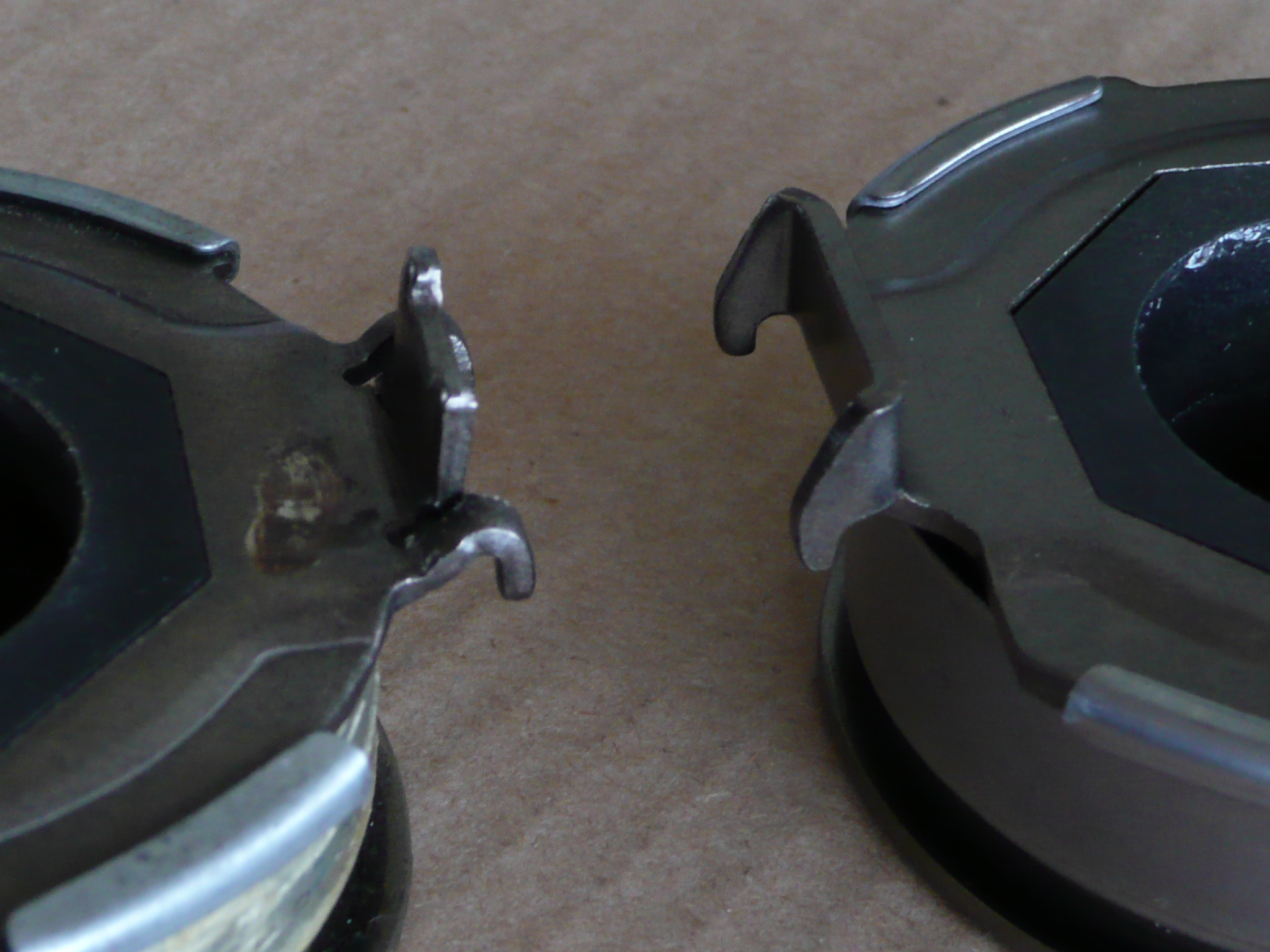
2.3 Fit the clips to the Subaru release
bearing adapter plate. The adaptor design has been revised as of March 2009 for
two reasons:
a.
To
make the bell housing design insensitive to the different length slave cylinder
pushrods which come from different suppliers (despite there being only one VW
part number for the slave cylinder assembly).
b.
To
make the adaptor accommodate both the old and new designs of NTN Subaru release
bearing (the design changed around the end of 2008). This picture shows the differences (left = old,
right = new).
2.4 Fit the Subaru release bearing to the release bearing adapter plate with the two wire clips.
2.4.1 Hook
the central part of the clip around the Subaru bearing.
2.4.2 Hold
the bearing and adaptor together , and hook each end
of each wire clip into it’s groove in the adaptor the slots in the adaptor.
2.5 Prepare
the Cross shaft for use with the Subaru release bearing:
2.5.1 With the cross shaft removed from the bell housing, trial
fit the adapter plate / release bearing assembly onto the cross shaft fingers.
Rock the bearing on the fingers, and check that the adapter / bearing assembly
moves freely.
2.5.2 The arms welded to VW cross shafts are a
known weak spot when used with heavy duty clutches. Each arm is only spot
welded to the shaft in two places. Fully welding the arms on to increase
strength is common practice, and is highly recommended when installing a Subaru
conversion. Any welding process is suitable.
2.6 Fit the cross shaft and its bushes into
the new bell housing. The procedure is the reverse of removal, but with the
following exceptions:
2.6.1 Lightly grease the bushes
at both ends before refitting the shaft with
general purpose grease.
2.6.2 Aligning the plastic sleeve and the bush
inside it when refitting the cross shaft is important. The holes for the
retaining pin must be perfectly aligned with each other and with the hole in
the bell housing before the retaining pin can be fitted. The sleeve and bush
will be damaged if you get it wrong. It is not difficult – just make sure you
look into the tapped M8 hole in the bell housing to check that the holes are
aligned. Use a mirror if the transaxle is still fitted.
2.6.3 Screw the
retaining pin in by hand. If the holes are all aligned OK, it should go in
until the captive spring washer touches the casting. Carefully tighten it up to
15 Nm (11 ft lb).
2.6.4 Check the shaft turns smoothly. It should not
stick in any position. Wipe off any excess grease.
2.7 Very lightly
grease the release bearing guide tube.
2.8 Fit the
release bearing / adapter plate assembly to the new bell housing. If you are
refitting a used Subaru release bearing, DO NOT clean it with solvent, as this
can wash grease out of the sealed bearing. If the bearing does not rotate
smoothly, it needs replacing. Lightly grease the cross shaft release fingers
where they contact the bearing, slide the bearing over the bell housing guide
tube, rotate the shaft, and hook the bearing retaining spring clips around the
cross shaft release fingers.
2.9 Rotate
the shaft so that the bearing slides up and down the guide tube, to check that
everything moves smoothly.
2.10 If your VW has a
cable clutch:
2.10.1 Fit the pressed steel return
spring guide.
2.10.2 Fit the cross shaft return
spring around the release arm.
2.10.3 Fit the release arm and it’s retaining circlip.
2.11 If your VW has a
hydraulic clutch:
2.11.1 Fit the slave cylinder bracket around the
boss on the bell housing. Make sure it is squarely pushed up against the flat
face around the boss. Hold it in place with the M10 x 20 retaining screw and
washer, screwed into the steel insert in the casting. Tighten to 45 Nm (33 ft
lbs).
2.11.2 Fit the VW brace which ties the slave
cylinder to the transaxle casing just above the LH drive shaft flange. Don’t miss this out – the
bracket will rock on the bellhousing without the
brace, damaging the casting.
2.11.3 Fit the slave cylinder.
3. N/A
4. Installation:
Cross Shaft – Turbo (pull clutch)
4.1 Remove the clutch cross shaft from your VW
bell housing:
4.1.1 Un-hook
the cross shaft return spring (if your transaxle had a cable clutch) from the
release arm with a screw driver or similar. Make sure your fingers are nowhere
near the spring as you unhook it from the arm – it’s under quite a lot of
tension.
4.1.2 Remove the circlip from the end of the shaft.
4.1.3 Slide the release arm off the end of the
shaft. They can be very tight if corroded, but take care not to damage the
shaft. Although it is not re-used as with a turbo clutch, it is needed in
exchange to make another turbo shaft from. Heat may help if it really doesn’t want
to come off, but be aware that the bush which the shaft pivots in is plastic,
as is the sleeve which it fits into and the seals which keep the dirt out.
You’ll need to replace them if you heat the arm to remove it. A puller is a better idea. If you cant get the puller behind the arm, undo the circlip inside
the bell housing, sliding it along the shaft. This will allow you to slide the
shaft away out to give better access for the puller. Refit the circlip inside
the bell housing back into it’s groove once the arm is
removed.
4.1.4 Remove the fabricated slave cylinder bracket
and it’s brace rod from the bell housing if your
transaxle originally had an hydraulic clutch. They are not needed with a turbo
clutch, as they are replaced with new versions. The slave cylinder itself is
still used with the Subaru turbo clutch installation. If your
transaxle originally had a cable clutch (i.e. bay window bus), you will need to
convert to hydraulic.
4.1.5 Remove the threaded pin which retains the cross shaft bush from the bell housing. It’s M8, but has an 11mm head.
4.1.6
Push the shaft assembly
out from inside the bell housing until the bush assembly is clear of the
casting. The circlip and washer will push the plastic bush assembly out of the
bell housing. They can be a very tight fit. Pull the bush assembly off the
shaft, and the steel washer between the bush assembly and the circlip (which is
still on the shaft). The bush assembly consists of an outer plastic sleeve,
with a seal, then a bush, then another seal inside.
4.1.7 Check the shaft and plastic bush for wear,
and replace as necessary. They are usually in good condition, unless they have
been damaged during removal.
4.1.8 The shaft can now be removed from the bell
housing by sliding it across until it comes out of the bronze bush at the
opposite end, tilting it, then sliding it back out of the casting.
4.2 Fit
the new turbo cross shaft to the new bell housing following 2.6.1 to 2.6.4,
above.
4.3 Fit
the Subaru turbo release bearing onto the guide sleeve. If you are refitting a
used Subaru release bearing, DO NOT clean it with solvent, as this can wash
grease out of the bearing. If the bearing does not rotate smoothly, it needs
replacing. Turn the shaft so the release fingers engage in their slots in the
bearing.
4.4 Rotate the cross shaft back and forth, so
the bearing slides along the guide tube. Check that the release bearing moves
smoothly, and clears the cross shaft by at least 1mm.
4.5 Fit the new slave cylinder bracket to the
bell housing. The 4mm thick M10 spacer washer goes between the bracket and the
bell housing (see photo). Tighten the M10 bolt to 45 Nm (33 ft lb).
4.6 Fit the
M8 slave cylinder brace screw into the hole just above the left hand CV joint
drive flange.
4.7 Very
lightly grease the cross shaft release finger ends (just where they will
contact the bearing), and the release bearing guide sleeve with molybdenum
disulphide grease.
4.8 Rotate
the shaft so that the bearing slides back and forth along the guide sleeve.
Check that it all still moves smoothly.
4.9 Fit the release arm to the end of the
cross shaft. Lubricate the interface with an anti sieze
compound such as copper grease. This is VERY important - you may not be able to
get the engine out without drilling a hole in your bell housing if this join
seizes up.
4.10 Fit the VW T25 / Vanagon clutch slave
cylinder and pushrod to the bracket. Check that the bleed screw has not seized
up on the slave cylinder before fitting, and replace as necessary.
4.11 N/A
4.12 Bend the slave cylinder pipe to suit, and
tighten all the pipe fittings. If you have a late model with a plastic clutch
pipe, note that the banjo fitting in the end can be turned in the pipe to get
the best fit.
4.13
Bleed
the clutch if you have disconnected the slave cylinder during the conversion.
Because the slave cylinder has to be fitted with the pushrod end higher than
the bleed screw end for the turbo clutch, the slave cylinder must be unbolted
to bleed it. Hang the slave cylinder by it’s hose so
the bleed screw is at the highest spot, then bleed and refit.
5. Installation:
Preparing the Subaru Engine
5.1 Check
that the two engine alignment dowels have remained in the Subaru transmission.
Sometimes they stay in the engine. If not, either pull them out of the holes in
the engine, or knock the dowels out of the new bell housing. If you do remove
the dowels from your bell housing, make sure the casting is supported properly.
Place the dowel into a metal plate with a hole just bigger than the dowel.
Remove the dowel out of the casting from the opposite side with a hammer and
punch, or preferably a press. They are Loctited in,
so will be tight. Do not try to tap them out without properly supporting the
aluminium around the dowel on the opposite side
5.2 Manual Transmission Subaru Engines
(proceed to 4.3 if your engine is from an automatic transmission Subaru):
5.2.1 Remove
the clutch pressure plate from your Subaru engine. Undo the six M8 screws one
turn at a time, alternating across the pressure plate to avoid distorting it.
Note that Japanese M8 bolts have a 12mm head, not 13 like the rest of the
world. Lift the pressure plate away, and catch the clutch disc – it will fall
out.
5.2.2 Clean the clutch dust off the flywheel.
Clutch dust is dangerous - follow the precautions in either a VW or Subaru
manual on not inhaling any dust, and how to clean it off the components.
5.2.3 The input shaft pilot bearing in the centre
of the flywheel needs to be removed. There are various ways to do this:
i) The easiest way to
remove the Subaru pilot bearing is to pull it out with an internal bearing
puller on a slide hammer, if you have one, which most people don’t. You can do
the same job with an M6 nut and bolt, a claw hammer, a block of wood, and a
screwdriver:
Screw the nut onto the bolt, and hook the
head of the bolt behind the inner race of the Subaru pilot bearing. Put a flat
bladed screwdriver into the bearing too, to wedge the bolt head behind the
bearing Adjust the nut so that the claw hammer can be used to pull on the bolt.
Place a piece of wood between the hammer and the flywheel to avoid damaging
flywheel (see photo). If you have a dual mass flywheel LINK, be very careful to
only lever against the steel sleeve around the pilot bearing, not the flywheel
face itself. The photo shows the bearing being removed from a dual mass
flywheel.
ii) An alternative way to remove the bearing
from the flywheel is to tap it out from the opposite side. This means removing
the flywheel. The bearing is fitted in a through hole, also used to centre the
flywheel on the crank spigot. Eight M10 bolts hold the flywheel to the crank,
and unlike the VW engines, removing the flywheel does not disturb the crank oil
seal.
Most Subaru’s up to ’99 use hexagon headed
flywheel bolts. You’ll need to lock the flywheel to undo the bolts. Wedge a VW
flywheel lock tool in the ring gear teeth in the starter motor gap if you have
one – this works very well LINK. Alternatively use a very long flat bladed
screwdriver between two of the ring gear teeth to stop the flywheel turning
against the crank case. Remove the bolts and lift the flywheel off. Tap the
pilot bearing out of the flywheel, and refit the flywheel. Tighten the bolts
with a torque wrench to 69 – 74.5Nm (51 to 55 fl lb). Some low to medium
strength thread lock on the threads would not be a bad idea.
Note some ’00 and later Subaru’s use Torx Plus LINK headed flywheel bolts. These are a heavy
duty Torx design, and are NOT compatible with normal Torx bits – trying to undo them with a normal Torx bit is likely to break the bolt head. Torx plus bits are not easy to get hold of, especially in
the long length needed to remove a Subaru dual mass flywheel. If your engine
has Torx Plus flywheel bolts, you have two options.
You can either buy the correct Torx plus bit (size
50), and remove the flywheel, or get the bearing out with the flywheel still
attached (recommended – see i) above).
5.2.4 Fit
the wire ring into the pilot bearing hole. This stops the larger diameter inner
race of the new bearing rubbing against the end of the crank.
5.2.5 Fit
the new pilot bearing into the flywheel bore. Tap the bearing into place with a
suitable drift (be sure to push on the outer race only). A socket of the
correct outer diameter works well as a drift.
5.3 Automatic
transmission Subaru engines:
Automatic
transmission Subaru engines have no flywheel. Instead they have a torque
converter drive plate made from thin sheet metal. You will need to remove this:
5.3.1 Lock the drive plate so you can undo the
bolts without turning the crank, remove the rubber plug fitted into the
crankcase (behind the flywheel, below the throttle position sensor), Turn the crank
until you see a slot in the drive plate. Subaru dealers use a special tool, but
a large screwdriver works just as well. Put it through the slot to jam the
drive plate against the crankcase.
5.3.2 Undo the eight drive plate bolts. Remove the
drive plate.
You will need to find
a good used flywheel to convert your automatic transmission engine. See Appendix B. Try breakers, Subaru engine
specialists, or Ebay. Also get the
flywheel mounting bolts too if possible – the ones which hold the drive
plate will be too short for a flywheel. If you can’t get the bolts (Subaru part
No.800210660), they’re cheap from the dealers (£5 for all 8).
5.3.3 Follow 4.2.3 above for details of how to swap
the pilot bearing and fit the flywheel.
5.3.4 If
you are converting an auto engine, there is one other simple part that it would
be worth fitting too. Manual transmission Subaru engines have a cam belt guide
which is not fitted to the automatic models. It stops the belt jumping teeth on
the crank pulley LINK, and is fitted with two M6 x 1.0 x 10mm screws. Either
get a good used belt guide, or buy one from the dealer (Subaru part No.
13145AA001). They cost about £7. Set the clearance from the belt guide to the
belt at 1.0mm
6. Installation:
Fitting the Clutch:
The
procedure for fitting all types of Subaru Clutch is the same:
6.1 Clean the
flywheel friction face of all dust and grease with solvent degreaser on a clean
rag. Use brake or carburettor cleaner. Repeat for the pressure plate.
6.2 Check the flywheel for
scoring, cracks, or discolouration (suggesting overheating), and check that it
is not distorted with a straight edge. Replace as necessary. Repeat for the
pressure plate if using a second hand one.
6.2.1 If you have a 225mm Subaru pressure plate, check the disc fits between the strap rivet heads without touching them. There are a very small number of pressure plates (typically Valeo models) which the 228mm disc will not fit into without touching the rivet heads due to the 3mm diameter increase.
6.2.2 If your 228mm VW disc
does foul the rivet heads, you have two options. Replace the pressure plate
with one which clears the 228mm disc OK, or clearance the rivet heads slightly.
If you clearance the rivet heads, use a thin grinding disc, and don’t remove
more than necessary, otherwise you will compromise the strength of the clutch.
Picture 6-2-2.jpg shows a disc with the rivet heads clearanced.
6.3 Using either a VW
clutch centring tool, an input shaft from an old VW transaxle, or a universal centring
tool, align the clutch disc with the pilot bearing in the flywheel. Take care
to get the disc the right way around – with the side with the longer input
shaft splines nearest to the transaxle. This is very important. Usually they
won’t fit if the wrong way around.
6.4 Slide
the pressure plate over the centring tool and disc, and push onto the flywheel
dowels. Loosely (i.e. finger tight) fit on of the M8 screws near the top if
your engine is positioned with it’s crank axis
horizontal to stop the pressure plate falling off.
6.4.1 If you have a ‘push to release’ clutch with a
VW disc, fit the three curved shims between the pressure plate and the
flywheel. DO NOT fit these shims if you have a ‘push to release’ clutch with a Subaru
disc or any ‘pull to release’ clutch.
6.5 Check
for ‘O’ marks on the flywheel and pressure plate. These mark the imbalance high
spots of each, and must be positioned 120 degrees apart or more. Not all Subaru
clutches use these marks. Turn the pressure plate as necessary.
6.6 Loosely
fit all six M8 pressure plate screws.
6.7 Tighten
the pressure plate bolts to 17Nm (13 fl lb). Tighten each one turn at a time
alternating across the pressure plate to avoid distorting it. Remove the clutch
alignment tool.
7. Installation:
Joining the Engine and Transaxle / Fitting the Starter Motor
Once
the bell housing and clutch release parts have been fitted to the transaxle,
and the clutch, pilot bearing (and flywheel if converting an engine from an
automatic Subaru) parts have been fitted to the engine, you are ready to join
the two together.
The
bell housing is designed around the Phase II Subaru engine mounting flange, as
used from around 1999 onwards. This uses two studs and nuts, and six bolts. All
are M10 x 1.25. NOTE this is Japanese spec M10. If you are using bolts other
than the original Subaru parts, make sure they are the 1.25 pitch, not 1.5
(European M10)
Phase 2:
The bell housing is designed to use all the standard Subaru fasteners as used a
manual 2000 model. These are:
85mm
M10 x 1.25 with captive spring washer and plain washer – 4 off (Phase II), or 1
off (Phase I)
100mm
M10 x 1.25 with captive spring washer and plain washer – 2 off
M10
x 1.25 studs attached to engine, protruding 70mm, M10 x 1.25 flange nuts – 2
off
Phase 1:
If you are using an earlier Phase I design (as used up to around 1999), Again the standard fasteners from a manual model can be
used. You will also have three extra tapped holes in the bell housing – just
don’t use these. The fasteners you will need are also listed above.
Engines from automatic
Subaru’s converted to manual spec: The
length of one of the bolts used with automatic transmissions is different.
Instead of one of the 100mm bolts, you get a 130mm one. This is too long, and
does not have enough thread to allow it to be shortened to 100mm. Standard
bolts of the same length do not have enough thread length, so you need a proper
Subaru bolt, which we keep in stock.
7.1 Lubricate the input shaft splines with a
VERY small amount of general purpose grease. Use the absolute minimum amount,
and wipe off any excess.
7.2 Slide
the engine and transaxle together in as straight a line as possible, aligning
the two Subaru engine studs with the bell housing holes. Avoid bending the clutch pressure plate
diaphragm spring with the input shaft. Whether you need to join the engine and
transaxle before fitting the transaxle into your VW will depend on your VW
model (see the workshop manual), and what Subaru engine mounting system you are
using. Hoist / prop up the two so you can work around them safely whilst
joining the two together, as the workshop manual describes for a VW engine.
7.3 Rotate the crank very slightly as the two
go together to help the input shaft splines engage with the clutch disc.
7.4 Engage
the two dowels in the bell housing with the holes in the engine. If everything
is aligned correctly, the dowels should push part way into their holes easily.
Do not fit the bolts and tighten them to pull the engine towards the bell
housing. If force is needed, the something is out of line. Use the bolts only
to pull the dowels the rest of the way into their holes. They are an interference
fit, so will not push all the way in by hand.
7.5 Loosely
spin the nuts onto the two mounting studs.
7.6 Fit
the top bolt opposite the starter motor. Wind it all the way in but do not
tighten yet. Be very careful starting these bolts – don’t use power tools.
They’re screwed directly into aluminium, and could strip the threads very
easily if you are not careful.
7.7
If your engine is a Phase II model
with two studs and six bolts joining it to the transmission, fit the two
remaining bolts which don’t hold the starter motor. Again, don’t tighten yet.
7.8
If your engine is a Phase I, then
the original lower starter motor fastener will have been a stud screwed into
the bell housing (like the VW one). The equivalent hole is tapped in the new
bell housing. Fit the M10 x1.25 stud into this hole with thread lock, leaving
20mm of it sticking out.
7.9 If your engine is a Phase II, then the
original lower starter fastener will have been a through bolt passing through a
plain hole in the bell housing, and screwed into the engine block. The
equivalent hole is tapped in the new bell housing to suit Phase I engines (see
above). To fit the Subaru through bolt, you need to remove the tapping from
this hole. Using an electric drill (preferably a pillar drill) on a low speed,
and an 11mm bit, drill through this hole in the new bell housing to remove the
tapping
7.10 Fit the starter motor into the bell housing
with the remaining two bolts.
7.11
Torque all the bell housing bolts to
44 – 54 Nm (34 – 40 fl lb)
7.12
Check that both bell housing dowels
are correctly engaged in both the bell housing and engine.
7.13
If you are using a turbo clutch, you
need to latch the release bearing into the pressure plate. Until you do this,
pressing the clutch pedal will move the release bearing only, not the clutch.
To latch the bearing in to the pressure plate, unhook the slave cylinder
pushrod from the clutch release arm, and push the arm towards the slave
cylinder further than it would go with the pushrod in place. You should feel
the bearing latch into the pressure plate, after which there will be
significantly less free play in the movement of the clutch arm. Refit the
pushrod by pushing it into the slave cylinder against the spring, until you can
hook the pushrod socket back over the clutch release arm ball. See section 8, below for how to separate the
engine and transaxle with a turbo clutch.
8. Separating the Engine and Bell
With the ‘pull to
release’ clutch as used in all turbo Subaru’s, the release bearing and pressure
plate have to be latched together when the engine is installed (see point
7.12). This means that if you undo all the bell housing bolts to separate the
engine and transaxle, the two ate still held together by the clutch release
mechanism. Separate the engine and transaxle with a turbo clutch, the release
bearing must come out with the engine. To allow this, it has to be released
from the clutch release mechanism:
8.1
Undo the circlip, and remove the
clutch release arm from the end of the clutch release shaft, following assembly
steps 2.1.3 and 2.1.2.
8.2
Carefully ease the engine and
transaxle apart, twisting the clutch release shaft back and forth if necessary
until the release bearing slides off it’s guide tube.
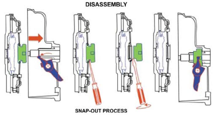
8.3 Remove the
release bearing from the pressure plate by inserting a flat bladed screw driver
and twisting it.
Appendices:
Appendix A: Subaru Clutch Information:
There are two
main types of clutch used on Subaru’s – the conventional ‘push to release’
clutches used on all naturally aspirated Subaru’s, and the ‘pull to release’
clutches used on turbo Subaru’s. See the web site of Subaru’s OEM clutch
manufacturer, Daikin, for an excellent
explanation of the differences between the two types of clutch (and lots of
other useful clutch information). Both
types can be used with an RJES bell housing, but a
different kit is required for each, as the clutch release mechanisms work
differently.
There are two types of
push clutch, which are not compatible with each others’ flywheel– the single
mass and dual mass flywheel versions.
There are two types of
pull clutches which are not compatible with each others’ flywheel – the 225/230mm
and 240mm versions.
Both push and pull
type clutches are also available in different sizes / ratings. For all clutch
types, make sure the Subaru clutch pressure plate you get matches your
flywheel. For the majority of cases this will mean using the following:
a.
A single mass flywheel from a naturally
aspirated or turbo Subaru with a clutch of 215, 225, or 230mm diameter. See Subaru Flywheel Types for more details.
b. A 225 or 230mm clutch pressure plate. Both
push (nat asp) and pull (turbo) types are suitable,
but you must use them in conjunction with the correct RJES
All of the above are
suitable for use with a 228mm VW bus clutch disc. For anything other than
normal road use, or for use with one of the higher powered Subaru engines, a
heavy duty aftermarket clutch disc should be seriously considered though.
215mm and
225mm Subaru Push Clutch:
The majority of
naturally aspirated Subaru engines use a 225mm diameter clutch disc. The size
refers to the outer diameter of the disc (or driven plate). This clutch design
is compatible with a VW disc from a 2.0 litre air cooled, or 1.9 / 2.1 litre watercooled bus (228mm). This is how the Subaru clutch is
joined to the VW input shaft, which has different splines. These discs are
widely available from VW specialists, but for some reason only as part of a
complete clutch kit. Non of the big VW parts suppliers
stock the individual parts for the 228mm clutch as they do for most of the
other clutch sizes. We stock VW OEM 228mm discs.
The 215mm clutch was
used on some 1.6 and 1.8 engines. It is interchangeable with the 225mm ones,
and could be used in a conversion (with the 215mm clutch disc from a late 1.6 type
1 engined or 1.7 or 1.8 type 4 engined
bay window bus). However one of the bigger Subaru clutches would almost
certainly be a better idea.
These clutches are
located by two 6mm dowels on 120 degree centres.
NOTE: In some 225mm Subaru clutch
pressure plates the VW 228mm disc fouls on the strap rivets by a tiny amount.
See above.
225mm and 230mm Subaru Pull Clutch:
The majority of
turbocharged Subaru engines which come from the standard turbo models (i.e. not
the WRX, GT, or STi models) use a 225mm diameter clutch disc.
The majority of
turbocharged Subaru WRX engines from 1993 onwards (but not those from all WRX
STi models, see below) use a 230mm diameter clutch
disc.
The sizes
refers to the outer diameter of the disc (or driven plate). These
clutches are both compatible with a VW disc from a 2.0 litre
air cooled, or 1.9 / 2.1 litre watercooled bus
(228mm). These discs, RJES part number XXXXXXXX
(VW part number XXXXXXX) are widely available
from VW specialists as part of a clutch kit. For some reason, they are quite
hard to get hold of individually.
These clutches are
located by two 6mm dowels on 120 degree centres. (the
same as the push clutches).
Note,
see below for information on uprated clutch arrangements. You may need one,
depending on how powerful your engine is, and what you intend to do with it.
240mm Subaru Pull Clutch:
Subaru
WRX STI’s from about 2002 onwards use a 240mm clutch to help handle the
increased power. They also use a different design of flywheel. The pressure
plate is a ‘push’ type, as with all the turbo Subaru’s but this is also
specific to the 240mm clutch. There is no 240mm VW clutch disc which can be
used for the conversion, and to the best of our knowledge there are no suitable
discs in use on production cars. It will be necessary to use a special clutch
disc with the 240mm pressure plate. We can get suitable clutch discs made (to
order).
Appendix B: Subaru
Flywheel Types
Single Mass Flywheels:
Ignoring the less
common dual mass and 240mm versions for now (more details on these below),
which each use unique flywheel designs, all other manual transmission Subarus use one of two types of flywheel(push or pull
clutch type). There are many minor variations of each. The only difference
between the two types in terms of compatibility is the bolt / dowel pitch
circle diameter. For ‘push to release clutches this is 268mm. For pull to
release it is 254mm. All have a flat face – the friction surface on which the
disc runs is the same face which the pressure plate screw holes are in. The
pressure plate is aligned with two dowels on 120 degree centres.
Some
of the minor differences between otherwise identical and interchangeable
flywheel types are as follows:
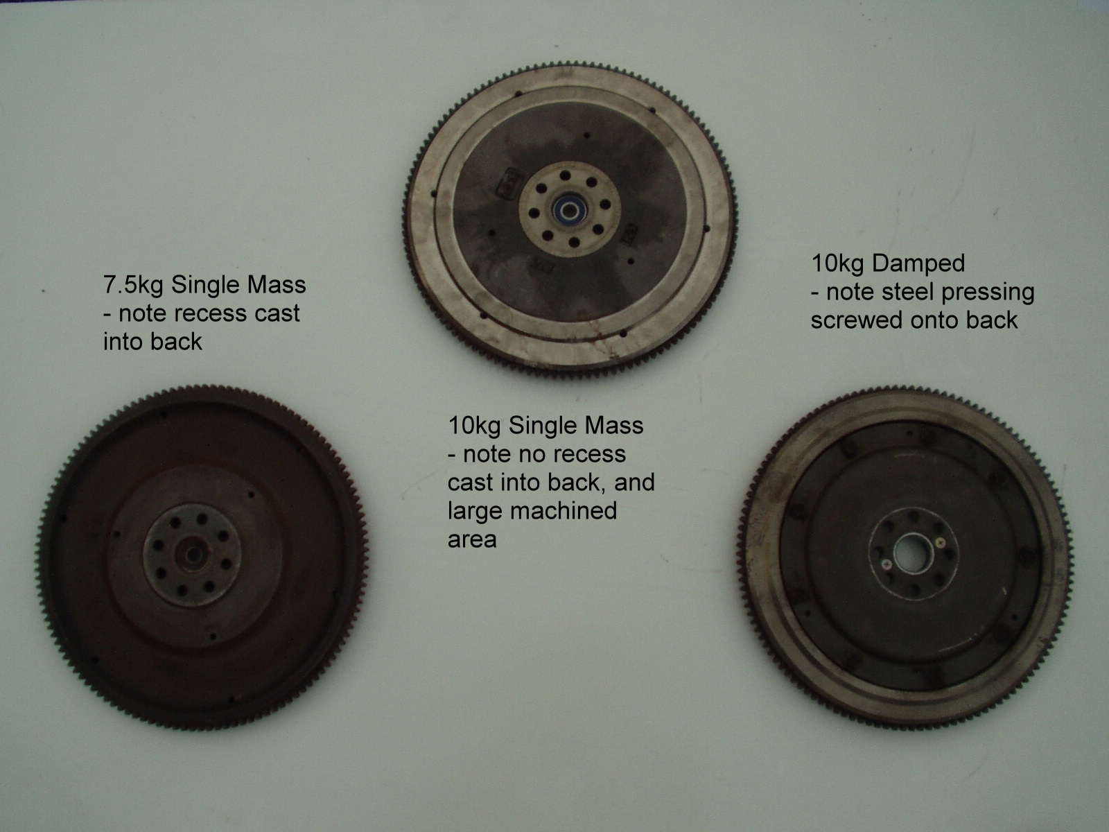
Weight: Some are lighter than others at 7.5 kg (ideal for race cars
or Beetles). Note that these are as light as some expensive lightweight
flywheels. Most weigh 10 kg (ideal for buses).
Damping: Some may have a simple torsional vibration damper built in (as
opposed to a dual mass flywheel). These are identified by a pressed steel plate
screwed onto the back.
See the clutch side view for three
different types, and the crank side view for how
to tell them apart.
The less common dual
mass flywheel and 240mm pull clutches can be used (see below for more details).
You have to use them in conjunction with exactly the right combination of other
parts though.
Dual Mass Flywheels:
From
2000 onwards, some naturally aspirated models of Subaru use a dual mass flywheel to provide better
torsional vibration damping between the engine and transmission. The dual mass
flywheels use a 228mm clutch disc, but a VW 228mm disc can’t be used.
The
pressure plates are unique to dual mass flywheels too, as the face of dual mass flywheels are not flat. They have raised
bosses where the pressure plate attaches, and use three dowels to align the
plate (as opposed to two on other Subaru flywheels).
Dual mass flywheels
are not suitable for anything other than normal use. If you intend to give the
clutch a hard time, you should do away with the dual mass flywheel, replacing
it with a single mass one. The reason is that the friction face of a dual mass
flywheel is very thin, and is more likely to distort due to heat if used for
anything other than normal use.
If you are using a
dual mass flywheel in your conversion, you will need a disc with no torsional
vibration damping springs. The torsional vibration damping springs are the coil
springs between the splined hub and the friction faces of the disc.
It will be necessary
to use an aftermarket disc with the VW splines in the hub, a 228mm outer
diameter, and no torsional vibration damping springs. It must have a Marcel
spring between the two friction faces and organic friction material. However,
if you know of a disc from a production car which may be suitable, please let
us know, thanks. To the best of our knowledge there is
no suitable disc from a production car.
We can get a suitable
clutch disc made to order. Please ask for details.
Pressure plates for
dual mass flywheels are unique to that application – those from a single mass
flywheel are not compatible.
Appendix C: Uprated Clutch Arrangements:
Uprating a Naturally
Aspirated Subaru Engine:
There are two options here – the standard ‘push to
release’ type clutch can either be replaced with a heavy duty equivalent, or it
can be swapped for the ‘pull to release’ type clutch from a Subaru turbo:
a) Uprating the
Naturally Aspirated Push Clutch:
Uprated clutches are available off the shelf as a direct
replacement for the Subaru naturally aspirated push clutches. These are mostly
made for the Impreza RS aftermarket in the US, and may be difficult, or
impossible find in the UK, as very few people tune naturally aspirated Subaru’s
apart from the Impreza RS, which was only sold in the US and Australia.
b) Converting to a Pull
Clutch from a Subaru Turbo:
Converting from the naturally aspirated push clutch to a Subaru
turbo pull clutch requires more than just a clutch change. The whole release
mechanism on a Subaru Turbo works the other way around, and has a totally
different release bearing design. The flywheel would also need changing for one
with a 254mm bolt / dowel PCD too
Uprating a Turbocharged
Subaru Engine:
Standard Subaru turbo clutches are available which can
handle around 200 to 280 bhp, depending on the specification. Many types of
aftermarket clutches are available to uprate the capacity to well over 500 bhp.
Clutch Discs:
The
standard VW 228mm clutch disc will physically fit into both 230mm and most
225mm Subaru turbo clutches. However, it not designed to handle the sort of
torque produced by Subaru turbo engines. If you are using one of the lower
powered turbo engines (around 200 bhp), a standard VW 228mm clutch disc may
still be OK, for normal road driving, but it is not recommended. If you intent
to drive it hard, or especially if you want to be able to do drag racing
starts, the VW disc will almost certainly not be up to it. Four large, dual
springs are used in Subaru clutch discs, as opposed to six very small single
springs in a VW disc. There are almost limitless options to get around this, as
explained below, in order of increasing cost:
a. Fit an uprated clutch
disc into the standard Subaru pressure plate.
This will increase the strength of the clutch, as a standard VW
disc will be the weak spot of the system. Apart from preventing disc breakage,
an uprated disc will never increase the torque capacity of a clutch.
There are no suitable discs available from other production cars.
What is needed is effectively a Subaru turbo disc with VW splines. Because of
the widespread use of Subaru’s in motorsport, and the road car tuning which
this creates, there is a huge selection of options for uprating a Subaru turbo
clutch. Options include changing from an organic friction material (as used in
all production cars) to a sintered metal, or cerametallic
disc. These do not slip as they engage, co do not produce the heat which often
damages organic clutches when abused. However, a direct consequence of them not
slipping is a very harsh on / off action. Most forms of motorsport use one of
these types of clutch, but they are generally considered too harsh for road
use.
We can get suitable special discs made to order with VW centre
splines, in almost any configuration, including rigid or torsionally
damped, organic, sintered, or cerametallic friction
materials. Please ask for details.
b. Fit a higher specification pressure
plate.
Higher specification pressure plates increase the torque capacity
of a clutch offer extra clamping force, at the expense of making the clutch
pedal heavier. The extra clamping force increases the torque capacity of the
clutch, so if your engine is still revving to the standard limit, but making a
lot more power due to increased boost, etc, then you will almost certainly need
an uprated pressure plate. Uprated pressure plates should be used with at least
a Subaru turbo specification clutch disc (in this case, a special with a VW
spline), and will often need a higher spec disc too, especially if you intend
to drive it hard or do drag racing starts.
c. The ultimate clutch specification is a multi plate clutch.
These are usually twin plate
designs, and can require a special flywheel too. They offer very high power
capacities without excessively high pedal pressure, and always use cerametallic, or sintered clutch discs, with their harsh on
/ off, ‘motorsport only’ action. They are very expensive, and would need two
special discs with VW splines, making them even more expensive.